When designing a PCB Prototype, the components you want to use are often not found in your favorite CAD software’s library, which made you have to add the component on your own. This short article will discuss how to make a library with all those components. For example, I’m going to make a library to help designing my LoRa APRS project design which I am improving. I have a LoRa module named “HDP14A ver 1.2”, an unusual module compared to the popular ones such as HopeRF or Ai-Thinker. To create this module, I have to make my own library. I will show you have to make it in KiCad 5
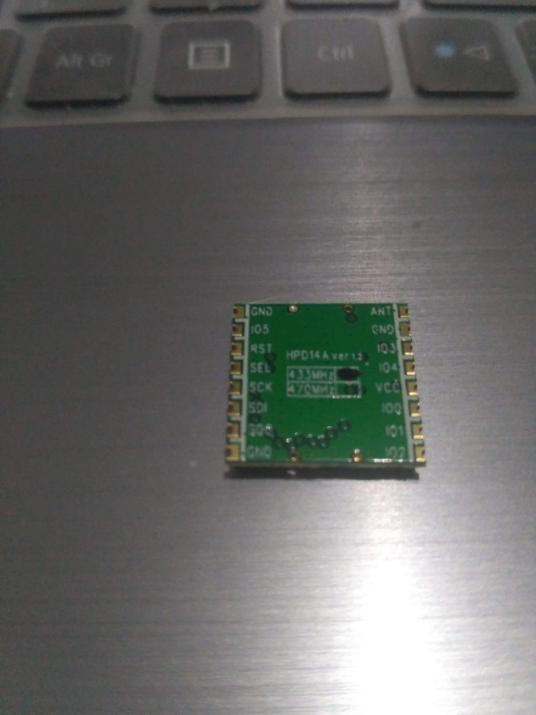
Picture 1. Physical Shape Of LoRa Module HPD14A ver 1.2
Create Project
Open KiCad and start by making a new Project using the ‘ctrl+N’ Shortcut. Give it a name and assign it to a folder of your choice. After opening that Project, click on ‘Symbol Library Editor’ as in Picture 2

New Library
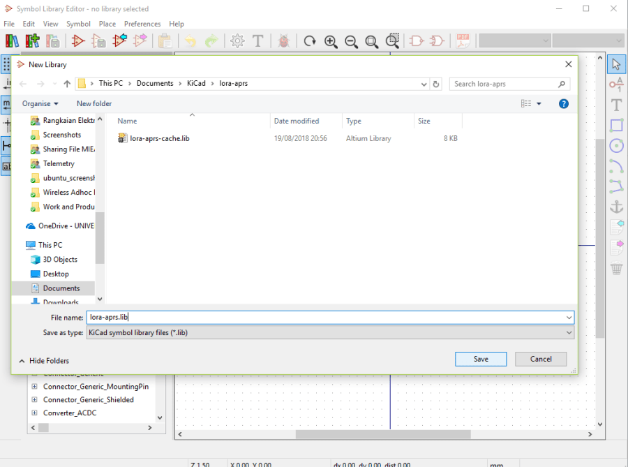
After opening the Symbol Library Editor, you can make a new library on your own. To make one, click on File > New Library. As an example, I will make a Library and named it with lora-aprs.lib. After clicking on Save, you can choose to save it as a library for this project only, or as a global library
Create a Component
After making a Library, the next process is to create the component. You can do that by clicking on ‘Create New Symbol’ button, or by going to Symbol > New Symbol. You will then be asked to choose what Library is going to be used to save this new component you will create. After selecting the appropriate Library, press the OK button

Add Pins on Symbol
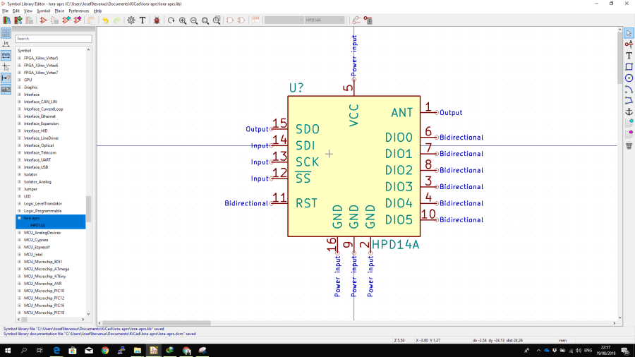
After creating the components and naming it (mine is HPD14A), the next process is to add pins on the symbol. You can do that by going to Place > Pin to add pins on a new component. Adding pins can be done as shown in Picture 5. You can add the pin orientation, number, and name of the said pin. In addition, you can also change the type of the pin connection if it is an Input, Output, Bidirectional, Power, etc. After successfully adding a pin, you can configure its position and add a square with Place > Rectangle to make it available to be used

Picture 6 shows the completed result, a LoRa module symbol with 16 pins. The pins on the symbol are grouped according to each of its function. When you’re satisfied with the result, you can save it with Ctrl+S. This component will then be accessible for your project, so you can immediately use it for PCB design
Have fun trying KiCad!
