In the previous article, I discussed about several basic Spread Spectrum concepts while specifically talking about LoRa modulation and touching the topic regarding several parameters in LoRa. Those parameters in question are Spreading Factor, Bandwidth, and Coding Rate. The three parameters will determine how sensitive the LoRa receiver will perform and how fast the data transmission speed will be. I will shortly discuss them in this article, hoping that the readers will be able to understand the concept and implement it in a LoRa-based system
Figure 1. LoRa Signal Spectrogram through SDR reading (source: DecodingLora)
Symbol
As discussed before, LoRa is a chirp spread spectrum modulation. The transmitted data, which is a symbol, will be represented by a chirp signal with a frequency range from to , which is shown in Figure 1. In LoRa modulation, we can configure the symbol by changing the Spreading Factor and Bandwidth parameters. According to Application Note Semtech AN1200.22, one symbol will take of second to transmit, which is a function of Bandwidth and Spreading Factor can be shown with the equation below:
Bandwidth
Bandwidth is the frequency range of the chirp signal used to carry the baseband data. In Figure 1, the Bandwidth can be seen from the width of frequency used between to . Aside from that, Bandwidth can also represent chip rate from LoRa signal modulation
Spreading Factor
The value of Spreading Factor (SF) determines how many chips used to represent a symbol. The higher the SF value is, the more chips used to represent a symbol, which means there will be more processing gain from the receiver side. This will allow receiver to accept data signals with negative SNR value
Spreading Factor shows how many chips used to represent a symbol, with an exponential factor of 2. 1 symbol may consist of N chip where . A cyclic shift can be done to represent a bit and sent symbol. If there is N amount of chips, then the resulting symbol value may range from 0 to N-1, or that 1 symbol may represent SF bits
Coding Rate
LoRa modulation also adds a forward error correction (FEC) in every data transmission. This implementation is done by encoding 4-bit data with redundancies into 5-bit, 6-bit, 7-bit, or even 8-bit. Using this redundancy will allow the LoRa signal to endure short interferences. The Coding Rate (CR) value need to be adjusted according to conditions of the channel used for data transmission. If there are too many interference in the channel, then it’s recommended to increase the value of CR. However, the rise in CR value will also increase the duration for the transmission
Automatic Position Reporting System or APRS is a digital communication protocol between a large number of amateur radio stations that covers a wide area. APRS can be used to send several tactical information, such as weather, location, messages, and several special events or emergencies in real time. APRS system is made by Bob Bruniga (WB4APR) from over 25 years ago, but this system is still actively used by many amateur radio stations
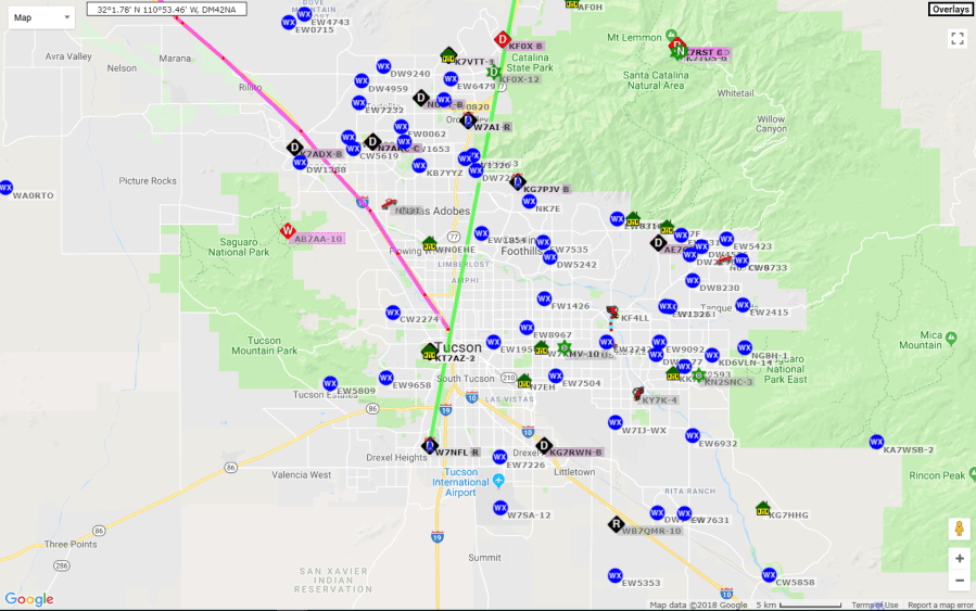
Like other amateur radio stations which still exists until now, APRS is already integrated through the internet. You can oversee many kinds of tactical information through APRS. One example of a website which shows APRS data is APRS.fi. In Picture 1, you’ll see many weather stations located in Tucson, Arizona, USA. One of the traditions for amateur radio stations in the United States is to provide public services, one of which is weather observation. Amateur radio station operators who owned weather stations use APRS to distribute the collected data
Although it’s called Position Reporting System, APRS itself isn’t intended as a GPS Tracker system. The development of APRS is triggered by GPS development back then, but APRS is actually a two-way communication system for real-time tactical communication
Picture 1. Screenshot of Amateur Radio Stations’ activities in Tucson, Arizona, USA
APRS Radio Network
After knowing about APRS systems and one of its applications, let’s talk about the components of an APRS system. In APRS systems, you may hear several terminologies such as:
Terminal Node Controller
Digipeater
APRS-IS iGate
Terminal Node Controller is the digital radio modem used in APRS. It’s usually based on Bell 202 Modem or Audio Frequency Shift Keying modem with baudrate of 1200 baud.
Digipeater is a digital repeater capable of resending data package which then allows many other stations could receive the information. Digipeater normally has a high power and placed on tall buildings to have a wide coverage area
APRS-IS iGate is an APRS connected to the internet so it can relay messages received through RF waveforms and entered them into APRS-IS server. From APRS-IS server, you can see the packages through several APRS websites or software
To enter the world of APRS, you have to own an amateur radio callsign. In Indonesia, you can register through “SDPPI Postel Kemkominfo”. You will have to enter a national exam for Amateur Radio (Ujian Nasional Amatir Radio) and if you passed, you will receive a certificate for that. Then, make sure you have the Permit to own an Amateur Radio Station (Izin Penguasaan Perangkat Radio Amatir). If you don’t want to do any transmission, tapping into APRS transmissions is allowed by anyone who has TNC and HT Radio
And that’s a small piece of information regarding APRS. I’ll add in more details on a different occasion
LoRa is a spread spectrum modulation technology patented by Semtech. LoRa is a derivative of Chirp Spread Spectrum (CSS) which lowers data rate to improve sensitivity. If you want to place LoRa in the OSI Layer, implementation of LoRa modulation exists on the physical layer and can’t be bound to other layers above it. This allows LoRa to adapt with several robust connections. This article is made to discuss several LoRa basic concepts as a reference to develop LoRa-based systems
Spread Spectrum Technology
For someone well-versed in Telecommunication, the Shannon-Hartley Theorem is no longer something foreign. This theorem explains about the canal capacity of a communication link using specific bandwidth with noise in the canal. I won’t write in the full theorem and details, but from the derivation of the mathematical formula, we can find that by increasing bandwidth, the performance between link communication with Noise-to-Signal ratio level will improve. In Spread Spectrum technology, you’ll usually hear that Noise-to-Signal ratio compared to Signal-to-Noise ratio because the power of a signal is usually below the noise floor
Just like the Shannon-Hartley theorem, bigger bandwidth can compensate for SNR degradation in the radio canal. In a Spread Spectrum system, the sent data is multiplied with Spreading Code, also known as Chip Sequence. Chip Sequence usually has a frequency far higher than the information frequency which resulted in a wider bandwidth when both signals are multiplied. On the receiver side, the received signal will be multiplied with the same chip sequence signal to obtain the original data
Picture 1. Spread Spectrum Illustration
LoRa Spread Spectrum
LoRa modulation provides alternatives for Spread Spectrum communication which are low power and low cost compared to the conventional Spread Spectrum technique. LoRa modulation uses chirp signal, which is a signal with a frequency which varies over time. By using this method, the complexity for the receiver side will be reduced. The output signal from this modulation matches the bandwidth used by the chirp signal
In LoRa modulation, the data with a certain bit rate that we want to transmit will be multiplied with a chirp signal with a certain Chip Rate. The Chip Rate is far larger than the data signal we want to send, which then became the Bandwidth from modulated LoRa signal
Aside from Bandwidth, there is also Spreading Factor. If Bandwidth shows chip rate, Spreading Factor shows how much chip is used to represent a symbol. Other than that, Spreading Factor also shows how many bits contained in a symbol
LoRa also has a mechanism called Forward Error Correction (FEC). FEC configuration can be done using the Coding Rate parameter. Just like a normal radio communication, noise can affect the performance of a system. By adding redundancy using FEC, the LoRa-based system designer can decrease the bit rate to increase the system’s reliability
To design a LoRa-based system, you have to pay attention to these three parameters to get an appropriate bit rate, decent enough range, and a nice reliability
Edit Aug 05/2018: The terminology in Spread Spectrum parameter had been corrected to make it more accurate
Bluetooth is one of the simplest communication modules which can be bought at a relatively cheap price. HC-05 Bluetooth Module can be easily found in many online shop websites around fifty thousand rupiahs. Before we further out discussion, I’ll talk about several Bluetooth basic concepts
Introduction
Bluetooth is a wireless technology standard for short-distance communication. Bluetooth uses 2.4 GHz frequency, which is a free-to-use frequency channel, with a low power limitation. Bluetooth standard encompasses quite a lot of protocols, one of which is RFCOMM Protocol. The Bluetooth Module which we usually find normally uses this protocol. RFCOMM Protocol is pretty popular because there is a lot of APIs available using this protocol. In addition, this protocol, commonly called as Emulation Port, can be integrated to many applications using RS-232 as its communication interface
Generic Bluetooth RFCOMM Modules
After knowing several of Bluetooth basic concepts, it’s time to see how Bluetooth works directly. For this demonstration, I’ll try using Bluetooth Module: Tokopedia (Disclaimer: No intention of promoting).
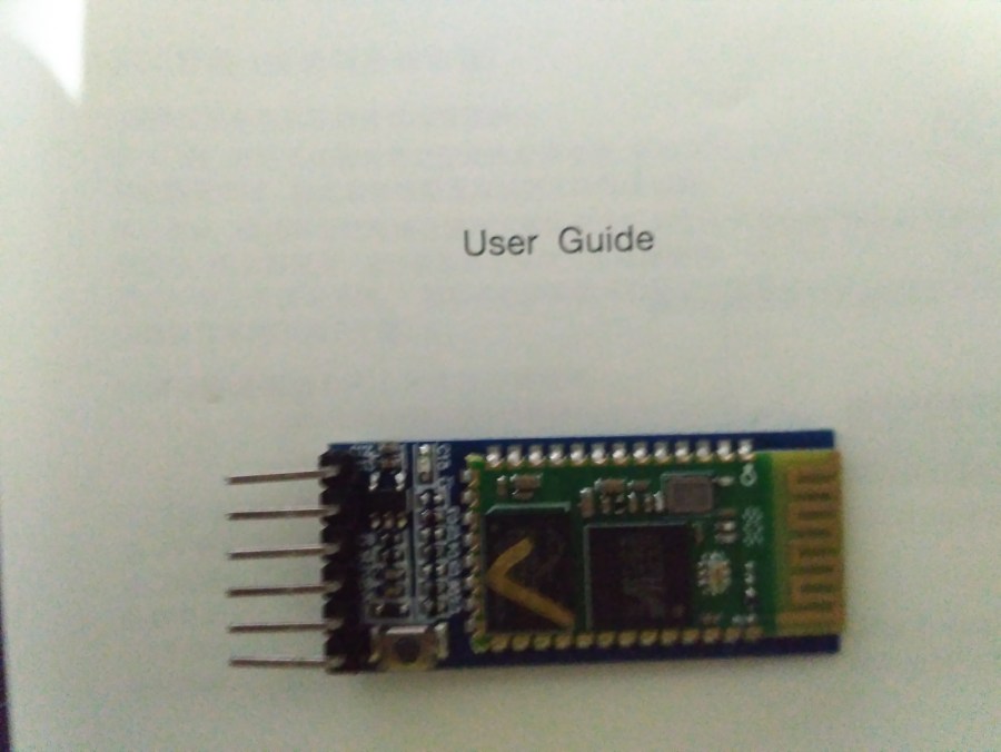
Picture 1. Bluetooth HC 05 Module
The Bluetooth Module as depicted in Picture 1 is a Module based on Bluetooth Chip BC417. This module has several output pins such as STATE, RX, TX, GND, +5V, and EN. To use this module, it’s enough to connect the RX, TX, GND, and +5V pins.
The 5V pin, or VCC Pin, in this module is actually connected to the LDO Voltage Regulator in this Bluetooth Module Board. I tried to see what kind of Regulator is being used, but it’s pretty hard to find a datasheet for this SMD component. Before I talked about how AT programming commands are, I’ll test the serial port using this Bluetooth Module first
Connect the Bluetooth TX pin with RX Raspberry Pi, RX Bluetooth with TX Raspberry Pi, VCC with +5V Raspberry Pi and GND with GND Raspberry Pi. I’ll turn on the minicom to open the serial port (/dev/ttyS0) using baudrate 9600. The test display result should be as shown in Picture 2
Picture 2. Serial Port Receive Outcome via Bluetooth
AT Commands Bluetooth
After finished testing the Serial communication, the next thing to try is the AT Commands. Several configurations such as Bluetooth name and PIN and also baud rate could be done through AT Commands. To do that, I made a short script in Python to execute this function. Before trying this script, make sure Raspberry Pi had been installed with Python and PySerial package (python-serial)
# apt-get install python-serial
Before I give the source code from AT Command Configuration, it’s important to know that entering AT commands can be done in three ways. The first is to give 3.3 Volt input to the 34th pin in the Bluetooth Module. This will make the module enter a Full AT Commands mode, where all AT Commands can be accessed and baudrate from the module is 38400. The second method is by pressing a button before the module turned on and make sure the button is still pressed as the configuration process continues (this is effectively similar to the first method), which makes the module enter a Full AT Commands mode. The third method is that after the module is turned on, press a button on the module and keep it pressed when doing the configuration. The module will then enter a Semi AT Command mode where the baudrate is still the normal serial communication baudrate (9600 baud default). If you forgot what baudrate you had set for your serial communication baudrate, it’s better to program your Bluetooth in Full AT Command mode
# attest.py
# Sending AT commands to Bluetooth HC-05

import serial
import time

bluetooth = serial.Serial("/dev/ttyS0", baudrate=9600, timeout=5)

bluetooth.write('AT+NAME=JosefMTD\r\n')
result = bluetooth.read(100)
print result

bluetooth.write('AT+UART=38400,0,0\r\n')
result = bluetooth.read(100)
print result
To use the program above, change “/dev/ttyS0” into “/dev/ttyACM0” if using PL011 Hardware UART from Raspberry Pi. Only use “/dev/ttyS0” if you’re using mini UART. Set baudrate according to the module’s baudrate or put in 38400 if you want to enter Full AT Command mode
To change the name and baudrate, Bluetooth module can be configured in a Semi AT Command mode, which is why my set of processes are to press a button, run attest.py script, and let go of the button when it finished
Picture 3. Output from program attest.py
That’s all from me this time, leave a comment if you have a problem in setting up the Bluetooth
Open Source Library adalah salah satu kelebihan dari KiCad, setiap minggunya, library KiCad di-update melalui GitHub dari KiCad. Artikel ini ditulis untuk menunjukkan cara instalasi library tambahan untuk KiCad, dan sebagai contoh akan menambahkan library dari pihak ketiga seperti Digi-Key ataupun Sparkfun Electronics. Library Digi-Key dan Sparkfun dapat diakses pada tautan di bawah ini:
Sebagai contoh, artikel kali ini akan menunjukkan cara menambahkan library Sparkfun pada KiCad 5.0.0 untuk Ubuntu 18.04
Cloning the Library via GitHub
Library dapat diakses melalui GitHub, di mana semua orang dapat membagikan library-nya dan dapat berkontribusi pada library open source yang ada di GitHub. Jika ada tambahan baru di library, menggunakan Git, perbaharuan versi menjadi lebih mudah dan tidak memakan banyak space pada hard disk, karena hanya file tambahan yang diunduh ulang dan bukan keseluruhan file. Untuk mengunduh library Sparkfun pada GitHub, pastikan Anda punya package git dan lakukan command di bawah ini:
Setelah selesai mengunduh Anda dapat melihat beberapa folder yang berisi Library dan pelengkap lainnya, dan juga dokumen tambahan. Contoh hasil unduhan library tersebut dapat dilihat pada Gambar 1.
Gambar 1. Hasil clone dari repositori library KiCad dari SparkFun
Adding the Library in KiCad
Setelah memiliki Library yang diinginkan, selanjutnya buka program KiCad untuk menambahkan library yang sudah diunduh. Sebelumnya, buat Project baru melalui menu File > New > New Project.
Akses “Environment Variable Configuration” pada menu Preferences > Configure Paths. Tambahkan Environment Variable baru menggunakan tombol “Add”, beri nama “KICAD_SPARKFUN_SYMBOL” dan tunjukkan letak foldernya melalui tombol “Browse”.
Gambar 2. Penambahan Environment Variable
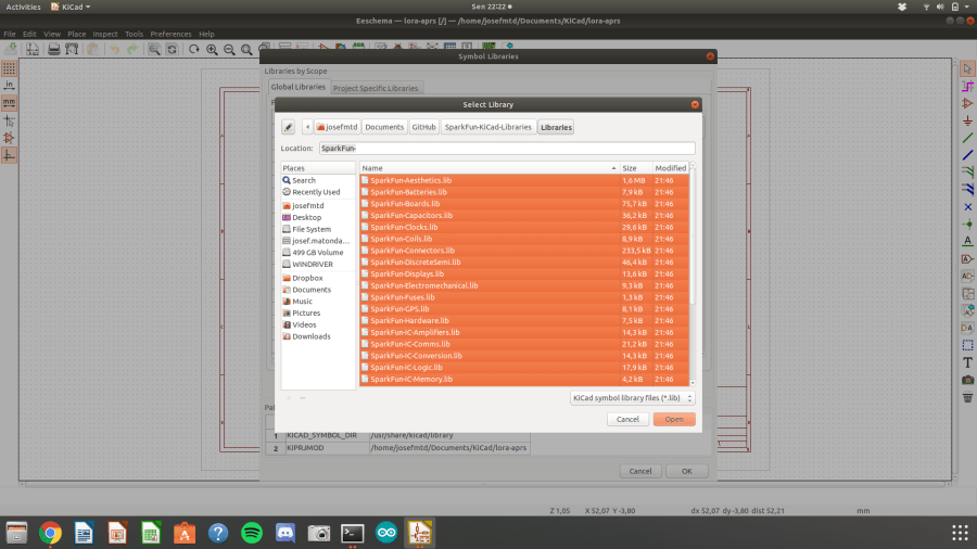
Setelah menambahkan Environment Variable, buka Eeschema (Schematic Editor) dan buka menu Preferences > Manage Symbol Libraries. Tekan tombol “Browse Libraries…” dan pilih semua library yang ingin ditambahkan lalu tekan “Open”
Gambar 3. Penambahan Library Symbol untuk Pembuatan Skematik
Buka Pcbnew (PCB Layout Editor) dan buka menu Preferences > Manage Footprint Libraries. Lalu, tekan tombol “Browse Libraries…” dan pilih semua folder .pretty yang ingin ditambahkan lalu tekan “OK”
Gambar 4. Penambahan Library Footprint untuk Pembuatan PCB Layout
Sekian artikel kali ini untuk menambahkan library pada KiCad, selanjutnya saya akan membahas pembuatan PCB sederhana menggunakan KiCad. Selamat mencoba KiCad!
KiCad adalah sebuah open source software untuk membuat skematik, layout PCB dan Gerber. KiCad dapat digunakan di Windows, Linux, dan macOS, dan dilisensikan di bawah GNU GPL v3. KiCad dibuat oleh Jean Pierre Charras, seorang dosen dari Universitas Grenoble. KiCad juga disponsori oleh CERN dan banyak perkembangan KiCad yang dilakukan oleh pegawai CERN. Jika Anda tertarik untuk membantu perkembangan KiCad, Anda dapat melakukannya melalui CERN.
Saya tertarik untuk mencoba aplikasi ini untuk melakukan proyek-proyek sederhana untuk hobi. KiCad menjadi pilihan yang sesuai karena bersifat open source sehingga siapapun dapat menggunakannya. Selain itu kelebihan dari KiCad adalah library yang diupdate setiap minggunya, Anda dapat mengakses library-nya dengan GitHub. Adafruit yang banyak menghasilkan modul-modul, maupun development board juga menggunakan KiCad untuk menghasilkan produk-produk mereka.
Ubuntu Installation
Saya mencoba instalasi kali ini dengan Ubuntu 18.04, Anda dapat melihat instruksi instalasi pada link ini: KiCad Ubuntu
Saya akan menjelaskan cara instalasi KiCad PCB v5 di Ubuntu 18.04, pertama hal yang Anda harus lakukan adalah menambahkan ppa berikut:
# add-apt-repository -y ppa:js-reynaud/kicad-5
(Ubuntu 16.04) Jika Anda menggunakan Ubuntu 16.04, lakukan apt-get update sebelum instalasi KiCad:
# apt-get update
# apt-get install kicad
Anda akan mengunduh sekitar 391MB dan setelah instalasi KiCad akan memakan disk space sebesar 4,970MB. Setelah selesai, Anda sudah dapat membuka KiCad melalui terminal, ataupun melalui Launcher.
Gambar 1. Terminal setelah instalasi KiCad dan tampilan aplikasi KiCad
Saya berencana memulai seri artikel membahas penggunaan KiCad, selanjutnya saya akan membahas cara menambahkan library dari GitHub KiCad. Selamat mencoba KiCad!
Do you want to try playing around with Raspberry Pi? Maybe you have encountered several problems such as no monitor to configure Raspberry Pi, no keyboard to write the commands, or no LAN cable. Maybe you have the same problem as mine, owning Raspberry Pi Zero W which can only be accessed through Wireless, USB using micro USB, or mini HDMI. If you have Raspberry Pi Zero and want to start playing around with Raspberry, please read this guide to start installing your Raspberry Pi!
Picture 1. Raspberry Pi Zero Wireless
Instalasi Operating System Raspbian Stretch Lite
Several things you need to start are as followed:
Raspberry Pi Zero Wireless (make sure it’s not a Raspberry Pi without WiFi)
Micro SD Card (Class 10 is better so the Read/Write Disk operations are better)
2A Handphone Charger
Laptop with SD Card Reader (Micro-SD Adapter, if necessary)
Wireless Router or Mobile WiFi Hotspot
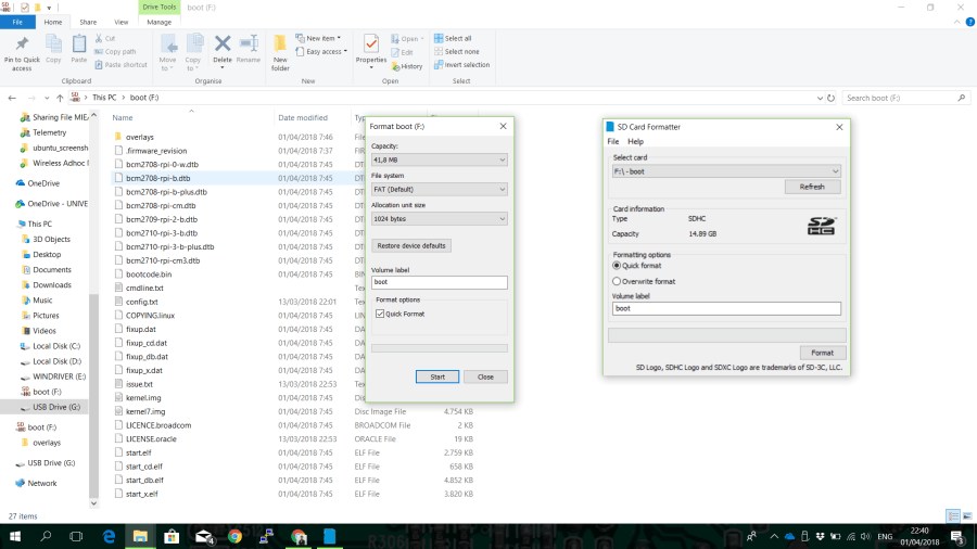
The first thing you need to do is to put in your SD Card into your computer, then format it if you have installed Raspbian on that SD Card. You can format it using SD Card Formatter (sdcard.org).
For a comparison, Picture 2 shows the formatting using quick format Windows dan SD Card Formatter. Windows Formatter can only format the F:\ partition in SD Card, while SD Card Formatter can format all of SD Card.
Picture 2. Formatting Comparison between Windows Formatter and SD Card Formatter
After doing Quick Format using SD Card Formatter, you can add Raspbian OS in SD Card. First thing you need to do is to download ZIP File from Raspbian OS Stretch Lite. Download from the Raspberry Pi official website for Raspbian Stretch Lite, with kernel Linux 4.9. There are two variants of Raspbian Stretch, which are the Desktop and Lite variants. Lite is the version without GUI, while the Desktop one had GUI so it can be connected to a monitor and keyboard and used like a normal computer.
After you have Raspbian Stretch Lite and a formatted SD Card, the next process is to flash Raspbian Stretch Lite on SD Card Formatter. My most favorable method is by using the Etcher program. This program can be downloaded from Etcher.io and it’s easy to use
Picture 3. Choosing Raspbian Stretch Lite to flash on SD Card using Etcher program
SSH Server dan WiFi Setup
To access Raspberry Pi without monitor or keyboard, you need an SSH Server and a WiFi connection. On the computer you’re using to configure Raspberry Pi, make sure you have an SSH client so you can use PuTTY.
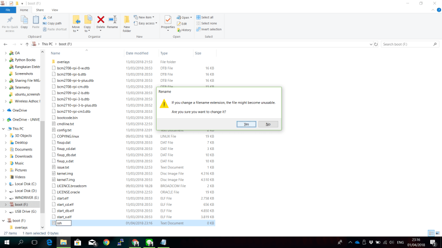
To turn on SSH, you need to create an “ssh” file on the boot partition in SD Card that you flashed using Raspbian OS. Make sure you made the ssh file without any extension (not even .txt). It didn’t need to contain anything, just ensure that there is a file named “ssh”
Picture 4. Installing SSH Server using SSH file without any extension in the SD Card for Raspbian
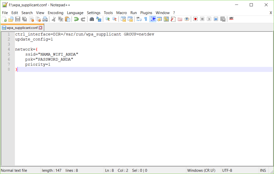
After adding the SSH server, the second thing you need to do is to create a “wpa_supplicant.conf” file on the boot partition. The content of this file is as follows:
Use Notepad to write those, and make sure you saved it as “wpa_supplicant.conf”, not in .txt extension. Picture 5 shows the result of creating “wpa_supplicant” file which is placed in the boot partition (F:\). Change NAMA_WIFI_ANDA with the SSID your WiFi is using, and PASSWORD_ANDA according to the WiFi password.
Picture 5. wpa_supplicant file configuration for the WiFi connection
After installing the Raspbian OS and adding the necessary files according to the instructions above, eject the SD Card and plug it into Raspberry Pi Zero.
Accessing SSH Raspberry Pi from PC
After ensuring that the created files are according to this tutorial, turn on Raspberry Pi Zero for the first time using the SD Card which had been installed with Raspbian OS and configured to be accessed using SSH through WiFi. Check the IP Address of your Raspberry Pi to access it using Raspberry Pi. You can use your Router’s DHCP Table to know which IP address is your Raspberry Pi’s. An example of that is shown in picture 6.
Picture 6. IP Address from Raspberry Pi Zero
After that, you can open PuTTY to access SSH from Raspberry Pi with the IP Address you obtained through your DHCP Router. You can login using
login as: pi
pi@192.168.0.7's password: raspberry
Make sure you follow the instructions above, using “pi” as your login name and “raspberry” for your password. After that, you can access Raspberry Pi Zero through SSH to change your password. You can do that using the command:
$ passwd
You’ll be asked to fill the old password (raspberry) and fill in the new one. After you filled it, make sure the SSH Server from Raspberry Pi is turned on permanently. You can do that by using this command as root (sudo):
# raspi-config
By accessing raspi-config, you’ll be shown the interface below like in Picture 7 on your PuTTY window screen. Direct the pointer to the “Interfacing Options” and press Enter.
After accessing Interfacing Options, choose P2 SSH to access SSH Server configuration. You’ll be asked “Would you like the SSH server to be enabled?” Choose Yes and press Enter. You’ll then see “The SSH server is enabled”. After you’re redirected to the front page, press Finish to exit. You’ll be able to access Raspberry Pi via SSH without using Monitor or Keyboard after this, but ensure that you have WiFi with the same SSID and Password as the configuration you had done
Still have more questions? Please ask in this blog post. Good luck experimenting with your Raspberry Pi.
Do you want to use Python 3.6 on Raspberry Pi? When you run Python in Raspberry Pi, the version called is usually v2.7. This blog post will discuss how to change the default Python 2.7 into Python 3.6.
Before I begin the tutorial, I want to explain one thing which is commonly seen in Linux tutorials, the ‘$’ and ‘#’ annotations. When writing a command in Linux Terminal’s common documents, both annotations are commonly used as prefixes. The reason for that is in Linux Terminal, when the user isn’t accessing root, will show the ‘$’ annotation. If the Terminal is showing ‘#’, then the user is accessing root. In the document which showed Linux commands, ‘#’ means the command must be accessed as root (or with sudo)
The first thing that can be done is to check if your default Python is on version 3.x or 2.x. You can use this command to make sure of that
$ python --version
Picture 1. Python version prior to upgrading to 3.6.4
There are a few things that must be done to change Python 2.7 into Python 3.6. The first thing is to ensure that several package dependencies must have been installed in Raspberry Pi. To make sure, you can use the command below
After executing those programs, you can download the source code for Python 3.6 from Python’s official website. Python 3.6 source code is provided in tar.xz, which means you have to unpack it. But before you download it with wget, make sure your file is in the /tmp/ directory, so it will be deleted after you reboot
$ cd /tmp/
$ wget https://www.python.org/ftp/python/3.6.4/Python-3.6.4.tar.xz
$ tar xf Python-3.6.4.tar.xz
Picture 2. Result after downloading and extracting the source code from Python 3.6.4
After you finished extracting as in Picture 2, you can see that the source code is at /tmp/Python-3.6.4. To continue with the installation, access Python-3.6.4 directory
$ cd Python-3.6.4
After opening the directory, follow the process below to install Python 3.6.4:
$ ./configure
$ make
# make altinstall
After installing Python 3.6, you’ll see that Python default is still the same as the previous Python (in my case, still 2.7.13). To change the default Python that is being used, you have to use update-alternatives. First, make sure that you know where to install Python 3.6. and that the installed Python 3.6 can be accessed. Use both these commands to know where Python 3.6 is
$ ls /usr/bin/python*
$ ls /usr/local/bin/python*
After knowing the position of executable Python 3.6, do update-alternatives to add Python 2.7.13 and Python 3.6.4 as Python alternatives. Picture 3 shows the output from command to find out where the executable files from Python2.7, Python3.5 dan Python3.6. Add all those executable Python-s as alternatives from Python
Picture 3. Python executable locations from root OS Raspbian directory
You will then find out the positions, which are /usr/bin/ for Python2.7 and Python3.5 and /usr/local/bin/ for Python3.6 which is just installed. Include the alternative /usr/bin/python using these commands:
After adding it as the order above, Python 3.6 will automatically become the default for Python. If you run call python –version, it will show the output like in Picture 4
Picture 4. Automatic version change for Python into Python 3.6.4
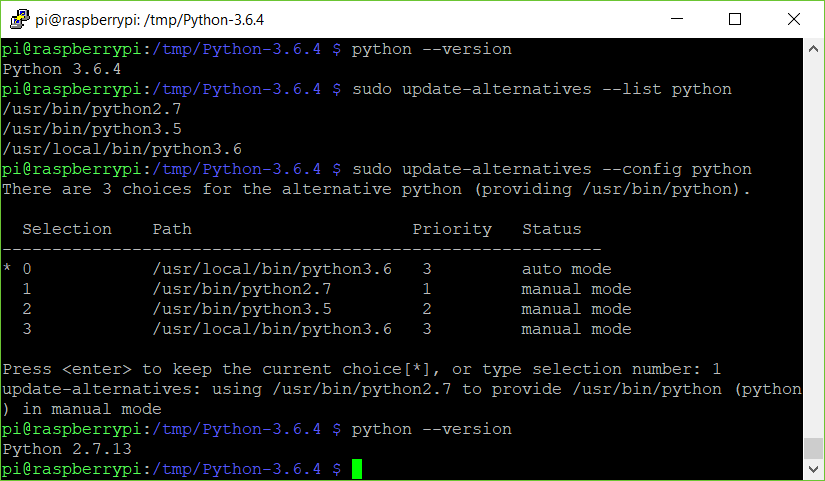
If you want to reconfigure your Python back into Python 2.7.13, you can run the command as follows:
After executing the commands above, you’ll be asked to input the number you want to use as your default Python. Type 1 if you want to use Python 2.7.13 because of one reason or another (for example, the library you’re using still uses Python 2.7). After selecting which version you want, you can check the default version using ‘python –version’ command dan the result will show like in Picture 5.
Picture 5. Changing back the default version of Python into Python 2.7.13
You can use the configuration commands below to select which version you want to use. You can do this if the newest Python version is available and you want to add it into Raspberry Pi. If you have any questions, don’t hesitate to ask them in this blog. Have fun experimenting!
Pada artikel sebelumnya saya membahas beberapa konsep dasar pada Spread Spectrum dan secara khusus saya membahas modulasi LoRa dan menyinggung beberapa parameter yang ada pada LoRa. Beberapa parameter tersebut adalah Spreading Factor, Bandwidth, dan Coding Rate. Ketiga parameter tersebut yang akan menentukan seberapa sensitif performa receiver LoRa dan seberapa cepat bit rate dari data yang dikirimkan. Parameter tersebut akan saya bahas secara singkat dalam artikel ini, dengan harapan pembaca dapat memahami konsep dan dapat mengimplementasikannya dalam merancang sistem berbasis LoRa.
Gambar 1. Spektrogram sinyal LoRa hasil pembacaan melalui SDR (source: DecodingLora)
Symbol
Seperti yang dibahas sebelumnya, LoRa adalah modulasi chirp spread spectrum. Sinyal data yang dikirim direpresentasikan dengan sinyal chirp dari sampai dengan yang dapat dilihat pada Gambar 1. Dalam modulasi LoRa, symbol yang dikirim dapat divariasikan menggunakan parameter Spreading Factor dan Bandwidth. Sesuai Application Note Semtech AN1200.22, satu simbol memakan waktu transmit sebesar yang dapat dilihat pada persamaan:
Bandwidth
Bandwidth adalah lebar frekuensi yang dipakai untuk memodulasi data sinyal. Pada Gambar 1, nilai Bandwidth ini dapat dilihat dari lebar penggunaan frekuensi dari dengan . Selain itu, Bandwidth juga merepresentasikan chip rate dari modulasi sinyal LoRa.
Spreading Factor
Nilai Spreading Factor (SF) menunjukkan seberapa banyak chip yang dipakai untuk merepresentasikan satu simbol. Semakin banyak chip yang digunakan untuk merepresentasikan satu simbol, maka semakin besar processing gain dari sistem receiver. Semakin besar nilai SF, semakin besar processing gain, hal ini memungkinkan receiver untuk dapat menerima sinyal data yang memiliki SNR negatif.
Spreading Factor menunjukkan banyaknya chip yang digunakan untuk merepresentasikan 1 simbol, dengan faktor eksponensial 2. Sehingga 1 simbol dapat terdiri dari N chip dimana , untuk merepresentasikan bit dilakukan cyclic shift untuk merepresentasikan simbol yang dikirim. Mengetahui terdapat N chip, maka dapat dihasilkan nilai simbol antara 0 sampai N-1, atau berarti 1 simbol dapat merepresentasikan SF bits.
Coding Rate
Implementasi modulasi LoRa juga menambahkan forward error correction (FEC), implementasi ini dilakukan dengan melakukan enkode 4 bit data dengan redundansi menjadi 5 bit, 6 bit, 7 bit, ataupun 8 bit. Menggunakan redundansi ini membuat sinyal LoRa lebih tahan terhadap interferensi singkat, nilai Coding Rate (CR) perlu diatur sesuai dengan kondisi kanal yang dipakai, jika terdapat banyak interferensi sebaiknya nilai CRditingkatkan. Namun perlu diperhatikan bahwa kenaikan nilai CR juga meningkatkan waktu transmisi.
Automatic Position Reporting System atau APRS adalah protokol komunikasi digital antara stasiun radio amatir dengan jumlah besar yang dapat mencakup area yang luas. APRS merupakan sistem radio paket yang dapat digunakan untuk mengirim berbagai informasi taktis, seperti cuaca, lokasi, pesan, dan berbagai event spesial atau emergency dalam waktu real time. Sistem APRS dibuat oleh Bob Bruniga (WB4APR) sejak lebih dari 25 tahun yang lalu, namun sistem ini masih aktif digunakan oleh banyak stasiun radio amatir.
Layaknya berbagai sistem radio amatir yang masih ada sampai sekarang, APRS juga sudah terintegrasi dengan jaringan internet. Anda dapat memantau berbagai macam informasi taktis melalui APRS, contoh website yang menunjukkan data APRS adalah APRS.fi. Pada Gambar 1, Anda dapat melihat banyak stasiun cuaca pada kota Tucson, Arizona, USA. Melihat banyaknya stasiun cuaca, perlu diketahui bahwa salah satu tradisi radio amatir di Amerika Serikat adalah layanan publik. Salah satu layanan publik tersebut adalah pengamatan cuaca. Operator radio amatir yang memiliki stasiun cuaca menggunakan APRS untuk membagikan datanya.
Walaupun bernama Position Reporting system, tujuan APRS ini sendiri bukan sebagai GPS Tracker system. Perkembangan APRS memang dipicu oleh perkembangan GPS pada zamannya, namun sebenarnya APRS adalah sistem komunikasi dua arah yang diperuntukkan untuk komunikasi taktis secara real-time.
Gambar 1. Screenshot aktivitas radio amatir Tucson, Arizona, USA
APRS Radio Network
Setelah mengetahui sistem APRS dan salah satu aplikasinya, selanjutnya akan dibahas komponen dari sebuah sistem APRS. Pada sistem APRS, Anda akan sering mendengar istilah sebagai berikut:
Terminal Node Controller
Digipeater
APRS-IS iGate
Terminal Node Controller adalah modem radio digital yang dipakai. Modem ini umumnya berbasis dari Bell 202 Modem, atau modem Audio Frequency Shift Keying dengan baudrate sebesar 1200 baud.
Digipeater adalah repeater digital yang mampu mengirimkan kembali paket data agar lebih banyak stasiun yang dapat mendengar informasi tersebut. Digipeater umumnya memiliki daya yang tinggi dan diletakkan pada gedung tinggi sehingga dapat memiliki jangkauan yang luas.
APRS-IS iGate adalah perangkat APRS yang terhubung dengan internet sehingga dapat me-relay pesan yang diterima pada gelombang RF dan memasukkannya ke server APRS-IS. Setelah dari server APRS-IS, Anda dapat melihat paket-paket tersebut melalui berbagai website APRS ataupun software APRS lainnya.
Untuk memulai memasuki dunia APRS, hal pertama yang perlu dipastikan adalah Anda sudah memiliki callsign radio amatir, jika di Indonesia, Anda dapat mendaftar melalui SDPPI Postel Kemkominfo. Anda akan mengikuti Ujian Nasional Amatir Radio, lalu jika lulus Anda akan menerima Sertifikat Kecakapan Amatir Radio, lalu Anda dapat mengurus Izin Amatir Radio. Setelah memiliki Izin Amatir Radio, pastikan untuk mempunyai Izin Penguasaan Perangkat Radio Amatir. Jika Anda tidak ingin melakukan transmisi, mendengarkan transmisi APRS diperkenankan untuk siapapun, dengan modal TNC dan Radio HT Anda dapat memulai bermain dengan APRS.
Sekian informasi singkat tentang APRS yang bisa saya sampaikan, informasi lebih detail tentang masing-masing komponen dari APRS akan saya sampaikan dilain kesempatan.


![\displaystyle R_b = SF \frac{\big[\frac{4}{4+CR}\big]}{\big[\frac{2^{SF}}{BW}\big]}](https://s0.wp.com/latex.php?latex=%5Cdisplaystyle+R_b+%3D+SF+%5Cfrac%7B%5Cbig%5B%5Cfrac%7B4%7D%7B4%2BCR%7D%5Cbig%5D%7D%7B%5Cbig%5B%5Cfrac%7B2%5E%7BSF%7D%7D%7BBW%7D%5Cbig%5D%7D+&bg=ffffff&fg=111111&s=0&c=20201002)


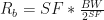
![R_b = SF \frac{\big[\frac{4}{4+CR}\big]}{\big[\frac{2^{SF}}{BW}\big]}](https://s0.wp.com/latex.php?latex=R_b+%3D+SF+%5Cfrac%7B%5Cbig%5B%5Cfrac%7B4%7D%7B4%2BCR%7D%5Cbig%5D%7D%7B%5Cbig%5B%5Cfrac%7B2%5E%7BSF%7D%7D%7BBW%7D%5Cbig%5D%7D+&bg=ffffff&fg=111111&s=0&c=20201002)
